Docooler XUH6362338938855GM
Docooler JINGSHA X99-8D3 Motherboard User Manual
Model: XUH6362338938855GM
1. Sissejuhatus ja lõppview
The Docooler JINGSHA X99-8D3 is a high-performance ATX gaming motherboard designed for LGA2011 V3 processors. It features four-channel DDR3 memory support, an M.2 NVME slot for high-speed storage, and multiple PCI-E expansion slots, making it suitable for demanding computing tasks and gaming setups. This manual will guide you through the installation, configuration, and maintenance of your motherboard.
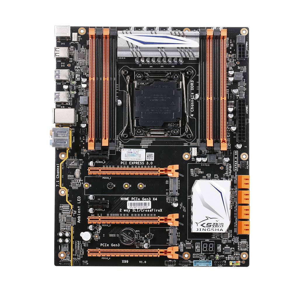
Joonis 1.1: Ülalt-alla view of the Docooler JINGSHA X99-8D3 Motherboard, showcasing its layout with CPU socket, RAM slots, and various expansion slots.
2. Põhiomadused
- M.2 NVME Support: Equipped with an M.2 hard disk port, supporting high-speed PCI-E NVME X4 for optimal operating system and application driver performance.
- Quad-Channel DDR3 Memory: Features 8 DDR3 memory slots across 4 channels, significantly improving capacity and performance, supporting up to 256GB.
- Digital Diagnostic Card: Integrated digital diagnostic card automatically tests hardware devices to ensure proper operation and assist in troubleshooting.
- Multiple PCI-E Expansion Slots: Provides 3 PCI-E expanded slots, configurable as X16/X8 to handle various workloads and multi-GPU setups.
- Vastupidav konstruktsioon: Built with a 10-layer PCB and high-quality capacitors for enhanced stability and heat resistance.

Figure 2.1: Diagram illustrating the six core technologies and features of the motherboard, including 4-channel DDR3*8, M.2 hard disk interface, digital diagnostic card, 7.1 channel audio, SATA3.0*8 interface, and Crossfire support.
3. Pakendi sisu
Palun veenduge, et kõik allpool loetletud esemed on teie pakendis olemas:
- 1x Docooler JINGSHA X99-8D3 Motherboard
- 1x SATA kaabel
- 1x I/O Baffle (Backplate)
- 1x CPU Fan Board
- A bag of screws
4. Tehnilised andmed
| Funktsioon | Spetsifikatsioon |
|---|---|
| Mudel | X99-8D3 |
| Vormitegur | ATX |
| Graphic Slot | PCIE3.0 16X*3 |
| Võrgukaart | Gigabit võrgukaart |
| Heli kanal | 7.1 kanal |
| CPU Type Support | LGA2011 V3 (2629V3/2649V3/2669V3/2678V3/2696V3/2676V3/2673V3) |
| PCB kihid | 10 kihti |
| Mälupesa | DDR3*8 |
| Maksimaalne mälumaht | 256 GB |
| SATA liides | SATA3.0*8, M.2 NVME |
| PS/2 Interface | Hiir/klaviatuur |
| Toiteallikas | 8 PIN*1, 24 PIN*1 |
| USB-liides | USB3.0*6, USB2.0*6 |
| Expanded Interface | PCIE 1X*2, M.2 WIFI*1 |
| Kauba suurus | 30.2 x 24.4 cm (11.89 x 9.61 tolli) |
| Kauba kaal | 930.5 g (32.82 untsi) |

Joonis 4.1: üksikasjalik view of the motherboard's rear I/O panel, showing PS/2 ports, USB 2.0, USB 3.0, Gigabit Network Port, and 7.1 Audio Ports.
5. Seadistamine ja installimine
Before beginning installation, ensure your system is powered off and unplugged from the wall outlet. Handle the motherboard by its edges to avoid static discharge.
5.1 CPU paigaldamine
- Locate the LGA2011 V3 CPU socket on the motherboard.
- Gently push down the CPU retention lever and swing it open.
- Align the triangular mark on your CPU with the corresponding mark on the socket. Carefully place the CPU into the socket without forcing it.
- Protsessori kinnitamiseks sulgege kinnitushoob.
- Kandke protsessori ülaosale õhuke, ühtlane kiht termopastat.
- Install the CPU cooler according to its manufacturer's instructions, ensuring proper contact and pressure.

Joonis 5.1: Lähivõte view of the LGA2011 V3 CPU socket on the motherboard, ready for CPU installation.
5.2 Installing RAM Modules
- Avage DDR3 mälupesade mõlemas otsas olevad klambrid.
- Joondage RAM-mooduli sälk mälupesa võtmega.
- Vajutage RAM-mooduli mõlemat otsa kindlalt alla, kuni klambrid oma kohale klõpsavad ja mooduli kinnitavad.
- For optimal performance, install RAM modules in matching pairs across the four channels as indicated in the motherboard manual or silkscreen.

Joonis 5.2: View of the eight DDR3 RAM slots on the motherboard, showing their arrangement for quad-channel memory configuration.
5.3 Installing Storage Devices (M.2 NVME & SATA)
- M.2 NVME SSD: Locate the M.2 slot. Insert the M.2 SSD at an angle into the slot, then gently push it down and secure it with the provided screw.
- SATA-draivid: Connect your SATA SSDs or HDDs to the SATA 3.0 ports using SATA data cables. Ensure the power supply SATA power connectors are also attached to the drives.

Figure 5.3: Close-up of the M.2 interface on the motherboard, highlighting its position and the PCI-E Gen3 X4 connection for high-speed data transfer.
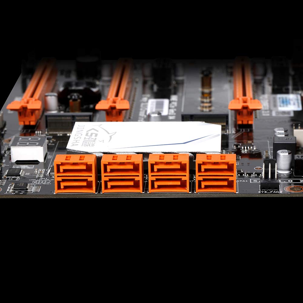
Joonis 5.4: View of the eight orange SATA 3.0 ports on the motherboard, providing ample connectivity for storage devices.
5.4 Toiteallika ühendamine
- Ühenda toiteploki (PSU) 24-kontaktiline ATX-toitepistik emaplaadi vastava pordiga.
- Connect the 8-pin CPU power connector (EPS12V) from your PSU to the 8-pin port near the CPU socket.
5.5 Installing Expansion Cards (PCIe)
- Locate the desired PCI-E 3.0 x16 or x1 slots.
- Eemaldage arvuti korpuselt vastav laienduspesa kate.
- Align the expansion card with the slot and press down firmly until it is fully seated. Secure the card with a screw to the case.

Joonis 5.5: Nurga all view of the motherboard, highlighting the three PCI Express 3.0 x16 slots and the smaller PCIe x1 slots, ready for graphics cards and other expansion cards.
6. Emaplaadi kasutamine
6.1 Esimene käivitamine ja BIOS-i seadistamine
- Pärast kõigi komponentide kokkupanekut ühendage monitor, klaviatuur ja hiir.
- Power on your system. During the initial boot sequence, repeatedly press the DEL or F2 key (common for JINGSHA motherboards) to enter the BIOS/UEFI setup utility.
- Kontrollige BIOS-is, kas kõik installitud komponendid (protsessor, muutmälu, salvestusruum) tuvastatakse õigesti.
- Konfigureerige käivitusjärjekord, et seada oma operatsioonisüsteemi installikandja (USB-draiv või DVD) tähtsuse järjekorda.
- Salvesta muudatused ja välju BIOS-ist. Süsteem taaskäivitub.
6.2 Operatsioonisüsteemi installimine
Follow the instructions provided with your operating system (e.g., Windows, Linux) to complete the installation process. Ensure you install all necessary drivers for the motherboard's chipsets, network, audio, and other components from the manufacturer's websaidilt või kaasasolevalt draiverikettalt.
7. Hooldus
Nõuetekohane hooldus tagab teie emaplaadi pikaealisuse ja stabiilse töö.
- Tolmu eemaldamine: Puhastage emaplaati ja komponente regulaarselt tolmust suruõhuga. Enne puhastamist veenduge, et süsteem on välja lülitatud ja vooluvõrgust lahti ühendatud.
- BIOS-i värskendused: Periodically check the Docooler or JINGSHA official website for BIOS updates. BIOS updates can improve compatibility, stability, and performance. Follow update instructions carefully to avoid damaging the motherboard.
- Draiveri värskendused: Hoidke oma süsteemidraiverid ajakohasena, et tagada optimaalne jõudlus ja ühilduvus uue tarkvara ja riistvaraga.
- Keskkonnatingimused: Operate the motherboard in a well-ventilated environment with stable temperature and humidity to prevent overheating and component degradation.
8. Veaotsing
See jaotis käsitleb levinud probleeme, millega võite kokku puutuda.
8.1 Toide puudub / käivitus puudub
- Ensure the 24-pin ATX and 8-pin CPU power connectors are securely plugged into the motherboard.
- Check if the power supply unit (PSU) is switched on and connected to a working power outlet.
- Verify that the front panel power button cable is correctly connected to the motherboard's header.
8.2 Ekraaniväljund puudub
- Ensure your graphics card (if dedicated) is properly seated in its PCI-E slot and has all necessary power cables connected.
- Check that your monitor cable is securely connected to the graphics card or motherboard (if integrated graphics are used, though X99 typically requires a dedicated GPU).
- Try reseating your RAM modules. Incorrectly seated RAM is a common cause of no display.
8.3 POST Code Display (Digital Diagnostic Card)
The motherboard is equipped with a digital diagnostic card (POST code display) that shows a two-digit code during boot-up. Refer to the motherboard's detailed technical documentation (often available on the manufacturer's website) for a list of POST codes and their meanings. This can help pinpoint the exact component causing a boot failure.

Joonis 8.1: Lähivõte view showing the integrated digital diagnostic card (POST code display) on the motherboard, which assists in identifying hardware issues during boot.
9. Garantii ja tugi
For warranty information and technical support, please refer to the documentation provided with your purchase or visit the official Docooler or JINGSHA webveebisait. Hoidke ostutõendit garantiinõuete esitamiseks.
Ask a question about this manual
Ask about setup, troubleshooting, compatibility, parts, safety, or missing instructions. Manuals+ will review the question and use this page’s manual context to help answer it.